Making the electrical connections to the track
Building a permanent Hornby model railway layout needs a consistent and reliable electrical power supply to all the sections of the track. The idea of one electrical connection from the power controller to each controlled track loop or section isn't good enough for a permanent model railway layout.
The best solution is to solder wires to each piece of track in the loop or section giving multiple soldered connections to the track. Small holes are drilled in the baseboard and the small wire tails passed through the baseboard. Then under the baseboard each of the wire tails can be connected to a length of wire running under the board following the track rails. This wire connects to the speed controller.
In this article we have soldered the wire tails to the fishplates to make the electrical connections. We have done this as fishplates with wire leads soldered onto them are commercially available.
By using insulating fishplates and switches, sections of your layout can be easily and reliably electrically isolated and connected. This allows multiple locomotives to be used on the same section of track giving a more realistic look and feel to your Hornby layout.
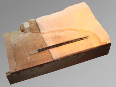
For this article we have produced a small N gauge demonstration layout built with spare materials left over from other projects. This base board is approximately 18" (450mm) x 12" (300mm). The scene is an old railway yard with a single terminating track adjacent to a hillside.

A fishplate with a short wire lead soldered into position. We have colour coded the wiring, red for the live feed and black for the ground feed.
This is an N gauge fishplate.
Underside of the fishplate showing the solder joint. The solder joint and wire are small enough to fit in the gap between the track rails and the baseboard.


This is the underside of two lengths of track joined with the fishplates. As can be seen there's plenty of room available for the connection.
The wire leads pass through small holes drilled through the baseboard to the underside where the electrical connection is made.
Where the wire tail pass through the baseboard needs to be fairly accurate to ensure there's no visible wires. Trial fitting of the track and marking where the holes are to be drilled is the best way to do this.
Here the baseboard has been measured and marked ready to drill the holes.


The wire tails are 1mm in diameter and so we drilled a 2mm hole for each wire.
2mm is small enough to not be visible and large enough for the wire tails to easily pass through the baseboard.
The track is fitted to the baseboard ensuring the wire tails pass through the prepared holes cleanly.

This is the underside of the baseboard with the wire tails shown. A couple of drops of super glue is used to secure the wire tails to the baseboard in and around the holes. These are the darker circles.
This acts a "strain relief" preventing any forces applied to the wire tails pulling them away from the fishplates.
The track power booster cable is fitted to the underside of the baseboard with lose fit "P" clips to the baseboard support structure. The "P" clips are secured with 1/2" long pan head No. 6 screws.
The track power booster cable will connect to all the wire tails for this section of track and connect to the speed controller.


The track power boost cable is 2 copper stranded wires joined by a thin plastic section which can be easily split.
The track power boost cable is divided where the electrical connections to the track wire tails is to be made.
The track power booster cable is stripped of its insulation while keeping the copper strands uncut. This "centre stripping" method ensures the main copper wires are continuous for the whole of the controlled section.
Note that the centre stripped sections on the track power booster cable are offset from each other.
The wire tails to the track are stripped of insulation and the copper strands are twisted together.


The wire tails to the track are twisted around the centre stripped sections on the track power booster cable.
To ensure the correct polarity the black wire tail is connected to the the track power booster wire with the black stripe marking. The red wire tail is connected to the the track power booster wire with no marking.
The wire tails to the track and the track power booster cable are soldered together to form good electrical connections.


Each soldered joint is insulated with electrical insulation tape. We are not able to use heat shrink sleeving on these joints as the track power booster cable is centre stripped.
Each piece of insulating tape is stuck adhesive side to adhesive side to form a flag type insulated electrical joint.