Building a permanent Hornby layout base board
Building a permanent Hornby layout needs a base board onto which everything else is fitted, modeled and operated. The base board for Hornby layouts is generally flat and structural from which scenery, such as hillsides, can be based.
This article explains one way to build your own Hornby base board. This method requires little skill but will need some wood working capability.
For this article we have produced a small demonstration layout built with spare wood materials left over from other projects. This base board is approximately 18" (450mm) x 12" (300mm).
For this article we have produced a small N gauge demonstration layout built with spare materials left over from other projects. This base board is approximately 18" (450mm) x 12" (300mm). The scene is an old railway yard with a single terminating track adjacent to a hillside.

This is the completed base board assembly for our small demonstration layout.
This demonstration base board represents the corner of a much larger base board.

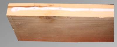
These are the raw materials for the small demonstration piece we intend to build. The base board itself is plywood with 9 layers and is 1/2" in thickness. The supports are plane timber of pine of 3" x 1".The materials are standard items available at your local DIY store.
The plywood board is marked out to show where the supporting structure will be fixed into place. With this demonstration layout we are building the corner of a large layout. There will also be another support timber part way along the length of the layout.
Here we have marked the holes to drill for the fixings. The fixings should be spaced around 12" apart and start near to the corner, say 2" from the edge.


A more detailed image of the marking out of the Hornby layout base board showing the marking of the holes to be drilled. The width of the 3" x 1" pine pieces is shown to ensure the screws will be central to the width of the wooden structure.
The fixing holes are drilled with a 4mm diameter drill bit. The drill bit used is shown in the picture.


A more detailed image of the fixing holes.
Then the fixing holes are countersunk by using an 8mm drill bit. This will ensure that the heads of the fixing screws will be just below the surface of the base board.


A more detailed image of the the fixing holes with the countersinking. It may not be pretty but that doesn't matter.
These are the fixing screws to secure the baseboard to the plane timber of pine 3" x 1" support pieces. The screws are No.6, 1 1/2" long and are standard items available at your local DIY store.


As well as the fixing screws the baseboard is secured to the support timbers with wood glue.
The wood glue is a standard item available at your local DIY store.
Here the wood glue has been applied to one of the pine support pieces. Use a generous bead of glue along the full length of the joint.
Excess glue can be wiped off easily once the joint has been made.

A more detailed image of the wood glue applied to one of the pine support pieces.
It may not be perfect but that doesn't matter.
This is the first support piece fitted to the base board with the wood glue and screws. The support piece is held into position by hand as the screws are driven into position.
We use a power screwdriver to fit the screws but they could be fitted by with a standard non-powered screwdriver if needed. It's just quicker with a power screwdriver.


A more detailed image of the fixing screw in the countersunk hole. You can see that the screw head is below the surface of the base board.
Again, it may not be perfect but that doesn't matter at this stage as the hole will be cleaned and filled later on.
Here the wood glue has been applied to the second support piece. Use a generous bead of glue along the full length of the joint including the joint with the first support piece.
Excess glue can be wiped off easily once the joint has been made.


This is the second support piece fitted to the base board with the wood glue and screws in the same way the first support piece was fitted.
With the second support piece in place it is clear that the two support pieces need to be secured together with screws at their joint.


Here the joint has been marked for drilling the screw holes. Note the holes are in the centre of the second support piece and not near to the upper and lower edges either.
Here the first support piece has the holes drilled for the required fixing screws. Again the 4mm drill bit was used.


Here the fixing holes have been countersunk, again with the 8mm drill bit. This ensures the screw heads are below the surface of the wood once the joint is complete.
These are the fixing screws for the corner joint. The screws are No.8, 2" long and are standard items available at your local DIY store.


This is the corner joint complete and the screws have pulled the joint tightly together. Again, the screw heads are below the surface of the wood.
Across the central part of the base board it will be necessary to fit additional wooden structure in the form of support pieces.
Here we have marked out the position of a centre support piece onto the base board and the front support piece.
Again, avoid positioning the screws close to the edges of the wooden support pieces.


These are the fixing screws for the centre support pieces. As before they are the No.6, 1 1/2" long for the base board and the No.8, 2" long for the joint to the front support piece.
The holes have been drilled and countersunk as previously with the 4mm and 8mm drill bits.
Here the wood glue has been applied to the centre support piece. Use a generous bead of glue along the full length of the joint including the joint with the first support piece.
Excess glue can be wiped off easily once the joint has been made.

This is the completed base board assembly for our small demonstration layout.
All the assembly joints are glued and screwed to give this baseboard as much strength as possible for the materials used.
This is the underside of the completed base board assembly for our small demonstration layout.
Excess glue on the underside is of no importance at all.


The holes drilled and countersunk for the screws that secure the baseboard to the support sections are filled and sanded to give a continuous smooth surface to the baseboard.
We used standard domestic decorating filler available from your local DIY store.
The baseboard is now complete and ready for some landscaping and track laying.